Network Simulation
Task 1
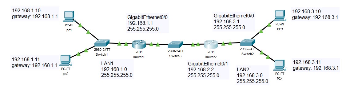
First connect the topology of the network
Then, set the ip address of PCs
PC1 IP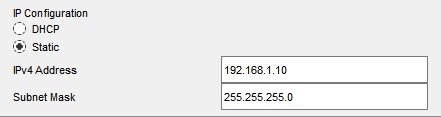 | PC2 IP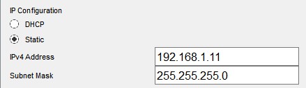 |
|---|---|
PC3 IP | PC4 IP |
Set gatway of PC1 and PC2 as the ip address of the router1192.168.1.1

Set gatway of PC3 and PC 4 as the ip address of router2 192.168.3.1

Set the router 1 and router 2 interface ip address as
Router 1 Interface 0 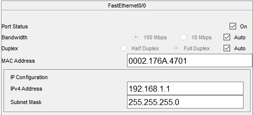 | Router 2 Interface 0 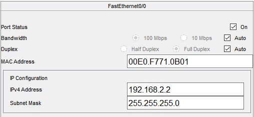 |
|---|---|
Router 1 Interface 1 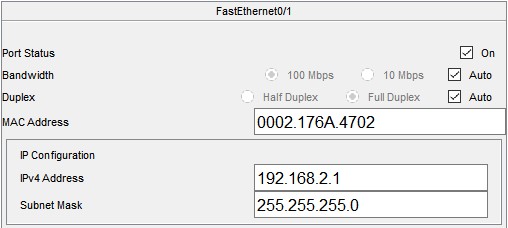 | Router 2 Interface 1 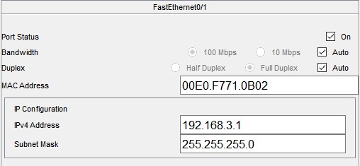 |
enable the router, and set the static routing as:
| Router 1 | Router 2 |
|---|---|
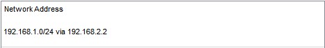 | 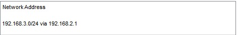 |
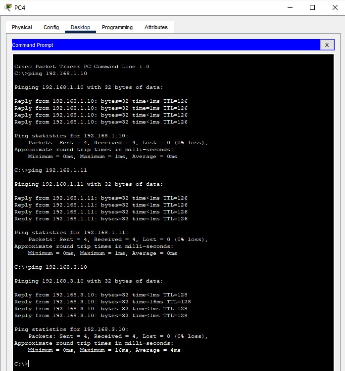
ping the other PCs and check the connection.
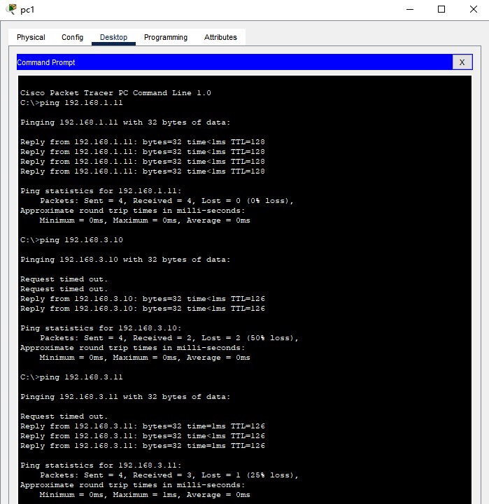 | 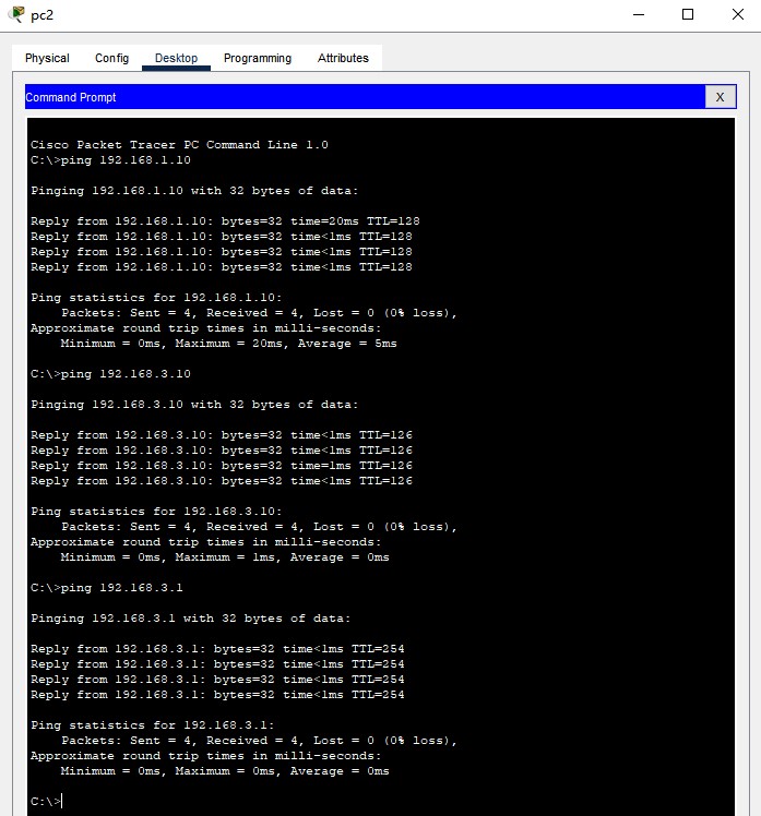 |
|---|---|
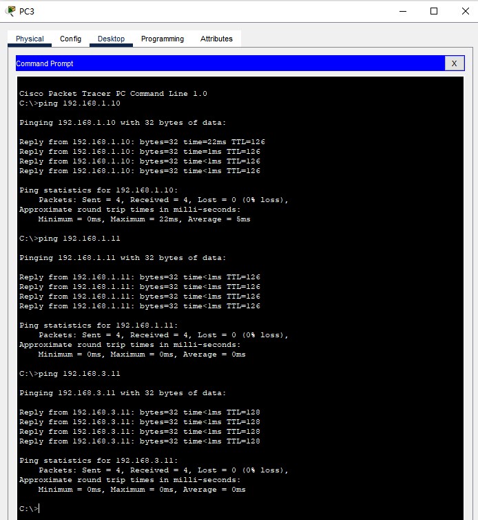 |  |
Task 2
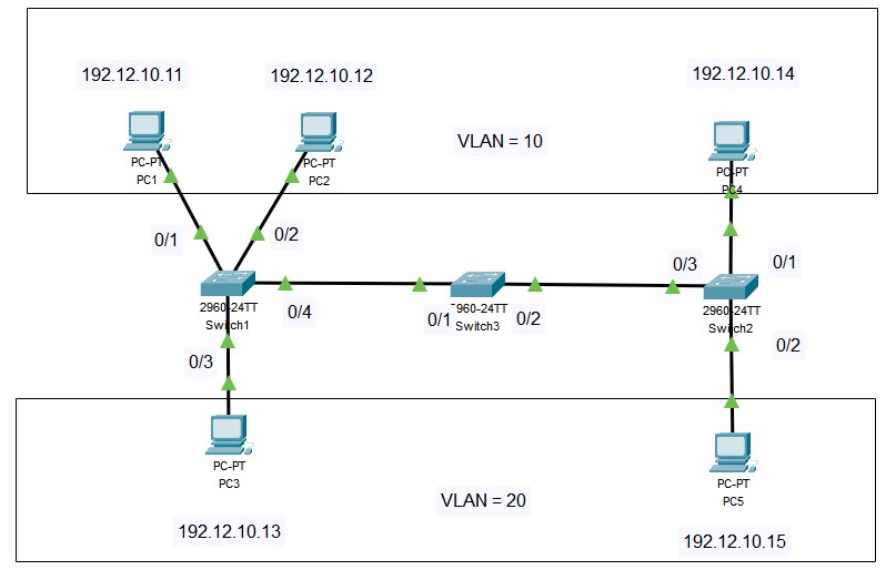
First connect the network like this:
Then, set the interface ip for PCs:
PC1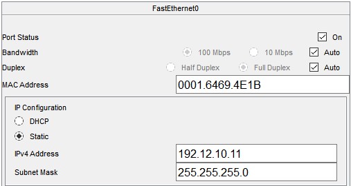 | PC2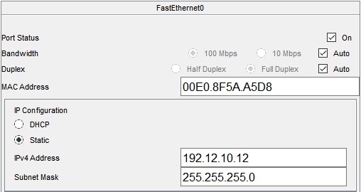 |
|---|---|
PC3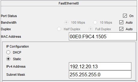 | PC3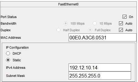 |
PC5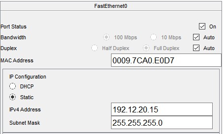 |
| Device | IP | VLAN |
|---|---|---|
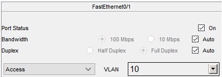
| PC1 | 192.12.10.11 | 10 |
| PC2 | 192.12.10.12 | 10 |
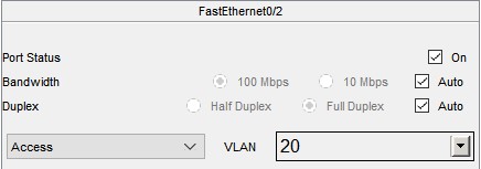
| PC3 | 192.12.20.13 | 20 |
| PC4 | 192.12.10.14 | 10 |
| PC5 | 192.12.20.15 | 20 |
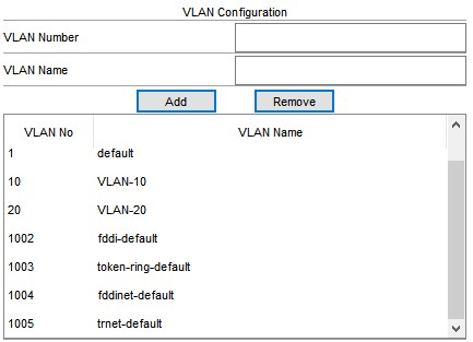
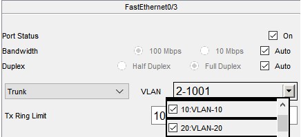
Then, add the VLANs 10:VLAN-10 and 20:VLAN-20 in all three switches
| Switch 1 to PC1 | Switch 1 to PC2 | Switch 1 to PC3 | Switch 1 to Switch 2 |
|---|---|---|---|
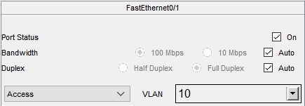 | 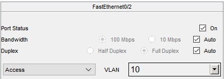 | 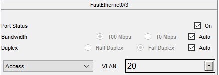 | 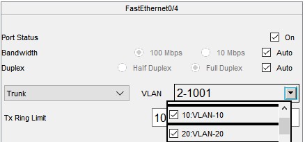 |
| Switch 3 to Switch 1 | Switch 3 to Switch 2 |
|---|---|
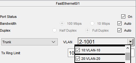 | 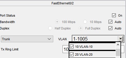 |
| Switch 2 to PC4 | Switch 2 to PC5 | Switch 2 to Switch 2 |
|---|---|---|
 |  |  |
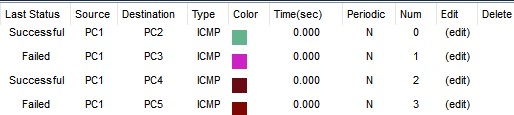
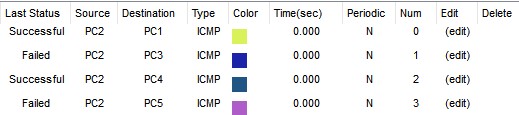
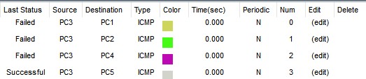
Finally, check the connectivity:
 |  |
|---|---|
 | 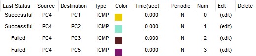 |
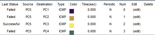 |
In conclusion, the VLAN has a isolation effect.
| PC1 | PC2 | PC3 | PC4 | PC5 | |
|---|---|---|---|---|---|
| PC1 | ✔ | ✔ | ❌ | ✔ | ❌ |
| PC2 | ✔ | ✔ | ❌ | ✔ | ❌ |
| PC3 | ❌ | ❌ | ✔ | ❌ | ✔ |
| PC4 | ✔ | ✔ | ❌ | ✔ | |
| PC5 | ❌ | ❌ | ✔ | ❌ | ✔ |
References
Learn how to use the Cisco Packet Tracer: https://www.netacad.com/courses/packet-tracer
Cisco Packet Tracer 8.2.1 Download: https://skillsforall.com/resources/lab-downloads